MKC TOOLS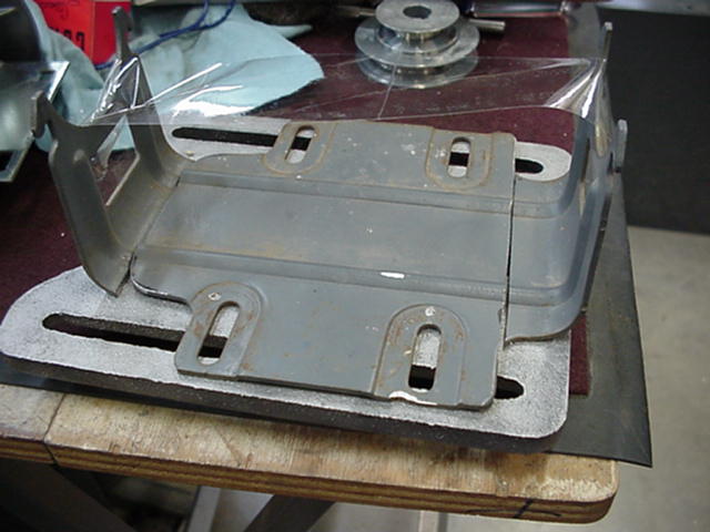
 To make a base for the treadmill motor
I used a regular resilient motor mount and cut it as
shown. I spread the bracket legs on the motor just enough
to stadle the two ridges in the motor base and welded it
in place. Notice that I moved it as far forward as possible
so that the shaft would be far enough out to possition the
pulley properly and give room for adjustment in the 10er
motor mount holes.
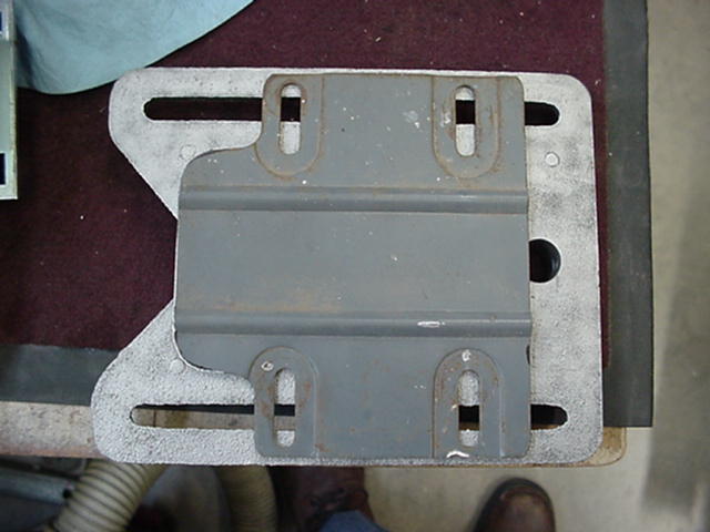
To make a base for the treadmill motor
I used a regular resilient motor mount and cut it as
shown. I spread the bracket legs on the motor just enough
to stadle the two ridges in the motor base and welded it
in place. Notice that I moved it as far forward as possible
so that the shaft would be far enough out to possition the
pulley properly and give room for adjustment in the 10er
motor mount holes. 
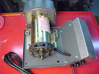
For the Surplus Center 10-1783 I had to do it a little differently. Since the base is not wide enough to line up with the slots in the 10er motor mount casting, I welded two heavy duty washers to the base at the edge of the treadmill motor mount. I used the rear holes in the treadmill motor mount to attach it to the controller plate with flat head screws. I drilled two more holes in the controller plate to line up with the 10ER motor mount slots. I built several units like this and they work great. 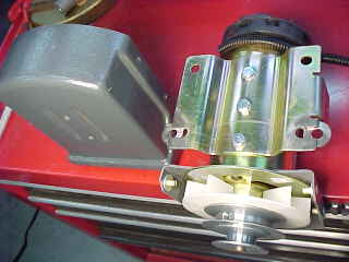
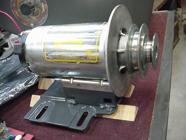
Here is another treadmill motor which had a more standard base but the hole spacing was not right for the 10ER motor mount. I just welded on two 1/4 x 1" straps with holes drilled to line up correctly. Also show is one of those threaded mount flywheel poly-v pulleys which I modified by cutting a standard v-belt slot on the metal lathe. This also worked out fine. 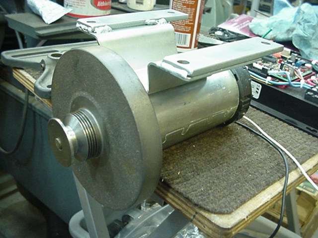
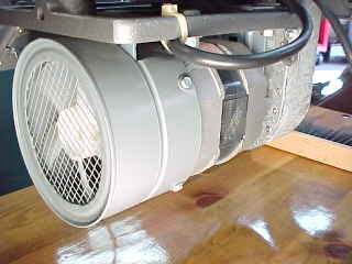
This was my first dc motor project for the 10ER. It was a GE series dc motor rated at 2 HP and from the Surplus center. It came with a controller plate drive so I had to make an enclosure for it. It had a cooling fan on the rear which was exposed so I built an enclosure for it from a coffee can. It worked great. I didn't have the tachometers at that time so I used a manual tach and marked the rpm settings around the control pot. Fortunately this motor was made to mount on a standard resilient motor base mount so I just had to find the appropriate base for it. 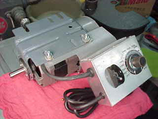
Contact by Email skip@mkctools.com Or Call 817-319-2297 MKC Tools Home |